MIL-PRF-62259B
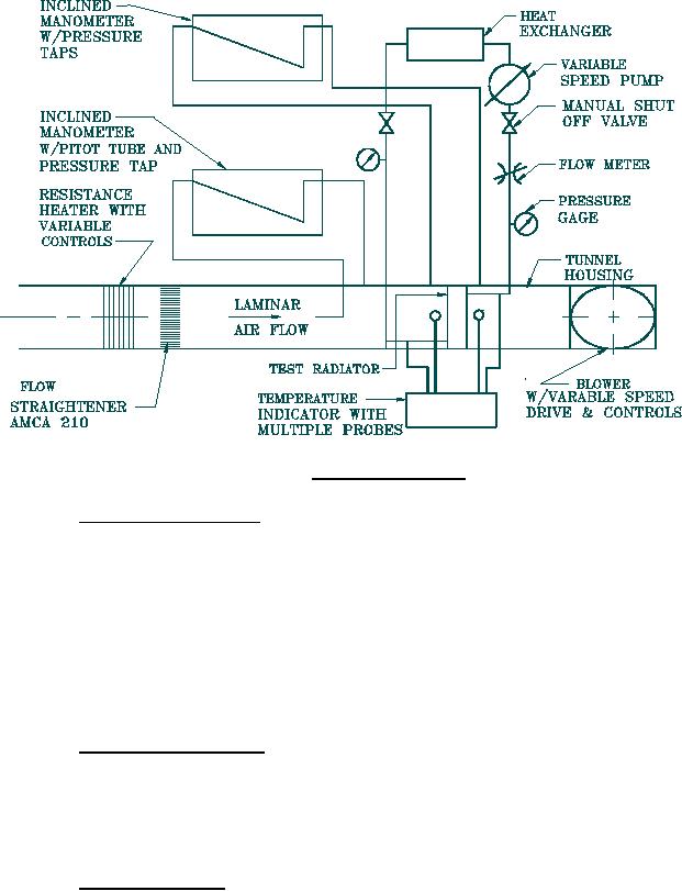
FIGURE 4. Alternate test setup.
4.3.3.2 Air flow resistance test. To determine conformance to 3.3.2, the radiator shall be
connected to a test setup similar to that shown in figure 3 or figure 4. With the system operating
as specified in 4.3.3.1, the air pressure drop across the radiator shall be measured at the same
time as the corresponding heat capacity. The pressure taps shall be in planes parallel to, and not
more than 4 in. (101.6 mm) from, the faces of the core. The air shall be measured in inches of
water (kPa) at an air density of 0.075 pounds per cubic foot (lb/ft3) (1.20 kilogram per cubic
meter (kg/m3)). The air flow resistance shall be based on the unobstructed area of the core and
the average inlet velocity is to be measured within three percent. Air flow values obtained from
testing which are greater than those shown on figure 1 shall constitute failure of the test.
4.3.3.3 Coolant flow resistance. To determine conformance to 3.3.3, the radiator shall be
connected to a test setup similar to that shown in figure 3 or figure 4. With the system operating
as specified in 4.3.3.1 and with a volume flowrate of the coolant of 94 gal/min (5.9 L/s), as
measured between the radiator inlet and outlet. A measured pressure drop across the inlet and
outlet ports of more than 3.0 psi (20.7 kPa) shall be cause for rejection.
4.3.3.4 Pressure cycle test. To determine conformance to 3.3.4, the radiator shall be
positioned and operated in its normal vehicle position in an ethylene glycol circulatory system.
Ethylene glycol shall conform to A-A-52624. The system shall maintain the ethylene glycol at a
maximum temperature of 250°F ± 10°F (121°C ± 6°C) measured at radiator inlet and outlet. The
radiator shall be subjected to the air pressure cycle approximated in figure 5. A cycle shall begin
9
For Parts Inquires call Parts Hangar, Inc (727) 493-0744
© Copyright 2015 Integrated Publishing, Inc.
A Service Disabled Veteran Owned Small Business